PIC32 Uart Driver and Protocol
Uart Driver and Serial Protocol Project
Introduction
For UC Santa Cruz's Electrical Engineering program, a concentration of Communication Signals and Systems, or Electronics and Optics must be chosen and a respective design elective based of the concentration. I chose electronics and optics with the design elective ECE 121, Microcontroller System Design. The final project for this course was to create a UART driver and protocol parser for the PIC32 microcontroller. This involved understanding the hardware architecture of the PIC32, how to interpret the family reference manual, to design a UART driver that interfaces properly to the hardware, and parses the data into packages based on its message ID. This is done on the ChipKit uno32 development board by Diligent, coded and debugged using MPLab X IDE.
Block Diagram
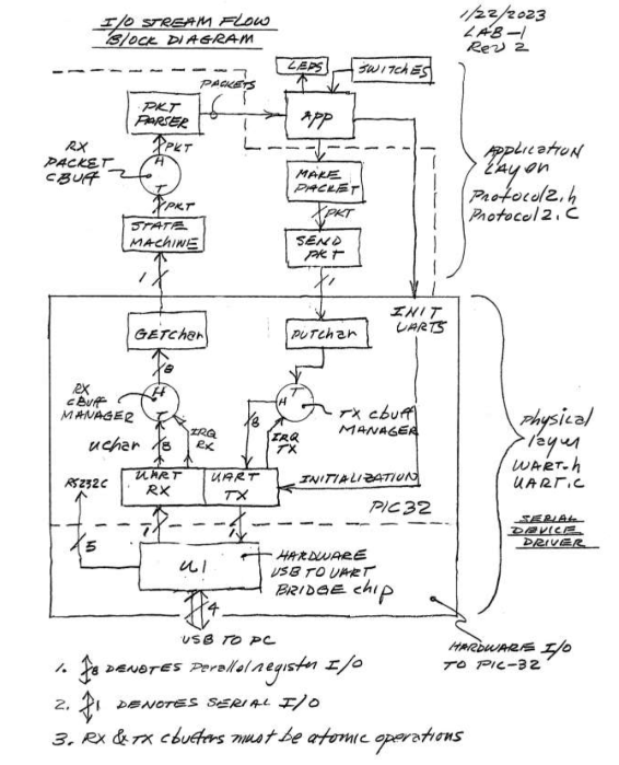
The project can be broken up into two distinct layers, the physical layer, and the application layer. The block diagram is featured below, and detailed descriptions for each layer follow. The two layers can be easily thought of as the physical layer being interrupting code based on the tx and rx registers, and the normal running code which is the application layer.
 Uart Driver and Protocol Block Diagram
Physical Layer
The physical layer consists of the UART bridge chip and is uart RX and TX registers (hardware components), the interrupt service routine functions, two instances of a circular buffer struct for rx and tx, and the Getchar and Putchar functions for adding or taking from the RX/TX buffers. This is necessary because of the limitations of the hardware register sizes.
typedef struct rxpT {
    uint8_t ID;
    uint8_t len;
    uint8_t checkSum;
    unsigned char payLoad[MAXPAYLOADLENGTH];
 }rxpADT;

typedef struct{
    int head;
    int tail;
    rxpADT data[PACKETBUFFERSIZE];
    int full_flag;
}packet_buffer;

typedef struct{
    int head;
    int tail;
    unsigned char data[BUFFER_SIZE];
    int full_flag;
}circular_buffer;
Character and Packet Buffer Structs
The heart of the physical layer is the UartInit function and the interrupt service routine (ISR) function which triggers the ISR depending on the status of the hardware registers. The code for the Init function and ISR are featured below.
void Uart_Init(void){
    IEC0bits.U1RXIE = 0;
    IEC0bits.U1TXIE = 0;
    U1MODE = 0;                     //clears control registers
    U1BRG = 21;                     //sets baud rate to generate 115200
    U1MODEbits.PDSEL = 00;          //sets no parity
    U1MODEbits.STSEL = 0;           //sets 1 bit stop             //uart enable
            //receiver enable
    IPC6bits.U1IP = 6;
    IPC6bits.U1IS = 0;
    U1STAbits.URXISEL = 0;              //rx flag raised when character is received
    U1STAbits.UTXISEL = 0;              //tx flag raised when tx contains space
    IFS0bits.U1TXIF = 0;
    IFS0bits.U1RXIF = 0;
    U1MODEbits.ON = 1;
    IEC0bits.U1RXIE = 1;
    IEC0bits.U1TXIE = 1;
    U1STAbits.UTXEN = 1;            //transmitter enable
    U1STAbits.URXEN = 1;
    return;
}

void __ISR(_UART_1_VECTOR)IntUart1Handler(void)
{
    int checker = 0;
    if(IFS0bits.U1RXIF)                                     //RX block
 {
        IFS0bits.U1RXIF = 0;                //URXDA is rx buffer sweet stop
        while(U1STAbits.URXDA && !is_buff_full(&rx_buffer))     //has room and data and buffer has room
 {
            add_to_buff(&rx_buffer, U1RXREG);               //add rxREG contents to rx_buff
            //LATE = 0b00000001;
 }
 }
    if(IFS0bits.U1TXIF)                         //TX block
 {
        IFS0bits.U1TXIF = 0;
        if(tx_busy)                             //if busy do nothing
 {
            //tx_collision = 1;
            //LATE = 0b00000010;
            //tx_busy = 0;
 }
        else
 {
            while (!is_buff_empty(&tx_buffer) && !U1STAbits.UTXBF)      //if not busy check if tx_buff has data and TX is not full
 {                   //UTXBF is 1 when TX is full
                unsigned char val;
                val = take_from_buff(&tx_buffer);           //print next char from tx_buffer
                U1TXREG = val;
                //LATE = 0b00000100;
                //tx_busy = 0;
 }
 }
 }
    //tx_busy = 0;
    IFS0bits.U1TXIF = 0;                            //lower flag for special cases such as first flag raise
}
UartInit and Iterrupt Service Routine
Application layer
As for the application layer, this consists of a serial protocol that verifies and creates packages via a state machine from the incoming characters (head, length, payload, tail, checksum, end). The state machine also parses the packages based on various IDs remakes the package and sends it back to the physical layer to be transmitted back out of the Uno32 development board. The IDs of each packet determine how they are parsed, the debug ID returns the date and time. The Ping ID returns the Pong ID and the rest of the message (payload) is converted from big endian to little endian and returned. The last two ID cases are the Set and Get IDs which based on the rest of the message (payload) sets or gets the status of lit LEDS on the board. For packages without these IDs, the none-affected payload is returned. Together both layers of the program work to correctly satisfy the project requirements.
Conclusion
This project was my first true embedded project and provided valuable insights into the limitations of hardware, and its respective software solutions. The hardware registers provided on the PIC32 are only 9 bits wide (if remembered correctly), and without the use of interrupting code to enqueue and dequeue this data to larger software buffers, data would be overwritten and lost. The software techniques used such as interrupts and linked lists provide a real-world solution to these limitations. The GitHub repo includes a more descriptive report of the project and all C source files.